Overview of network protocols


The 4-layer internet model is an abstract organization of the functions of a network communication. Each layer is implemented as an independent module and as such their implementation can change without affecting the others'.
Layer 4, the Application layer provides process-to-process communication for applications. Example protocols include HTTP, DNS, SSH, FTP.
Layer 3, the transport layer is responsible for the delivery of the data from source to destination. It can deliver them reliably or not (as we'll see). Example protocols are TCP and UDP.
Layer 2, the network layer is responsible for the forwarding of packets hop by hop via the routers of the network. Internet uses the IP protocol.
Layer 1, link layer defines how the individual bits are sent through the network and it's highly dependant on the underlying technology.
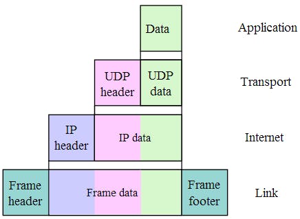
An important characteristic of network protocols is encapsulation. The bytes from the application layer get passed to the transport layer. Layer 3 then adds a special header (more on this later) to the data and calls it a segment. It then passes the segment to the network layer, which again, adds a special header to the entire payload and calls it a datagram. The final layer, link layer, adds a header and a footer to the payload it receives from the network layer and calls it an ethernet frame.
TCP (transmission control protocol)
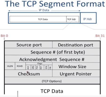
TCP is a reliable transfer protocol, meaning that it has mechanisms for checking that the bytes arrive at the destination, that they are delivered in order and that missing bytes are re-transmitted (a TCP payload is called a segment and each segment has a maximum length of 64KB including the header).
The source and destination port each 16 bits are used to determine which application to deliver the bytes to.
Sequence number (32 bits) indicates the start of the data in the stream of bytes. If we have a sequence number of 4000 then the data portion of this segment starts at byte 4000 in the entire stream of bytes.
Acknowledgement number (32 bits) is used to inform the sender which bytes it has received correctly and what byte it's expecting next. If it has received up until byte 4449 and expecting to receive from byte 4500, the acknowledgement number will be 4500).
HLEN (4 bits) specifies where the data portion starts. Or (more specifically), it's the size of the header in words (a word in this case is 32 bits or 4 bytes). The minimum size of this field is 5 (meaning 5 word = 5 4 = 20 bytes).
Reserved (6 bits) is not used.
Flags (sometimes written as control bits) (6 bits) are the various flags which can be set. For example SYN, ACK, FIN for establishing and tearing down of a connection.
Window size (16 bits) is used for flow control (more on that later).
Checksum (16 bits) is used to check for 1 bit errors. It's calculated over the tcp header + data.
Starting with Options #1 are the optional information. You can read more about them here.
A real TCP segment looks like this (this is a screenshot from wireshark and below it you’ll find the actual binary representation of the fields you see in the image). This is the first segment sent from my computer to a server on the web to establish the 3-way-handshake. More on this below.

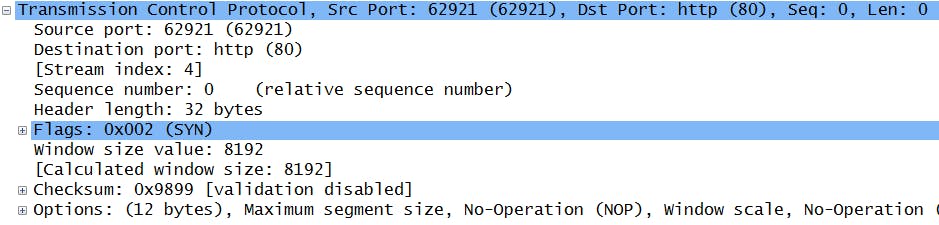
In this case (options) and (padding) are 0 and they wouldn't exit (no sense in having an extra 32 bits with zeros) but they are included just to show where they would follow. Below it we find the (data). What you can't see in the wireshark screen is the window size which is 8192 (in decimal) which corresponds to the binary number in the table.
To guarantee the delivery of the bytes, TCP must first establish a state (a.k.a. virtual link) between the two hosts. It does this with the 3-way handshake. The host who initiates the communication sends an empty segment (no bytes in the data portion) with the SYN flag set - it wants to synchronize with the other host. The other host sends a segment back with the SYN and ACK flags set - it acknowledges the received segment and wants to synchronize in the opposite direction (i.e. it establishes a state in the opposite direction). Lastly, the first host receives the segment and it sends back one with ACK set, acknowledging the received segment. Now the hosts can begin sending data to each other reliably. A more detailed explanation of the 3-way handshake will follow.
TCP flow control
Consider two hosts that want to send data to each other. One host can send at 10Mbps but another host can only receive at 1Mbps. There is no need for the first host to send data faster than the other host can receive because the extra 9Mbps will be dropped. Therefor we need some kind of flow control. There are two flow control mechanism: one is stop and wait, a very simple protocol, and another is sliding window which is more complex and offers better performance. TCP uses sliding window.
Note: stop and wait can be thought of as a sliding window protocol with a window size of 1 (more details below about what this means).
Stop and wait
With stop and wait the sender sends only 1 packet at a time and waits for an acknowledgement. Only when the acknowledgement arrives it sends another packet. If some times passes and it doesn't receive an acknowledgement, then it considers this a time-out (i.e. the packet didn't arrive at the destination for various reasons) and re-sends the pakcket.
If the packet is 10Kb long and the RTT is 50 ms (the round trip time is the delay it takes for the packet to be sent and for an acknowledgement for that packet to arrive at the sender) then with stop and wait we would only send at a rate of 200 Kbps (10 Kb 20; 20 represents the number of packets we can send in a second which is 1000 / RTT, or to put it differently, if you can send 1 packet every 50 ms, in a second you can send 20 because 50 20 is 1000 ms which is 1 second).
If we had a connection of 2Mbps we would only use 10% of the capacity of the link.
Sliding window
From above we know that sending only 1 packet at a time will only make use of 10% of the link rate. What the sliding window protocol enables us to do is to have n unacknowledged packets in flight for every RTT. If we can set n accourdingly then we can achieve the full 2MBps. To do that I'll take the same example from above.
To take full advantage of the 2Mbps link rate we should have sent at a rate of 2 Mbps / 20 = 100KB every RTT, or every 50 ms.
More details on the calculation: 2Mbps (or 2000Kb) / 20 = 100 Kb. To verify: 100 20 = 2000 Kb which is 2Mb (when referring to networking rates it is considered that 1Mb = 1000 Kb and not 1024). In packets, that is equivalent to 100Kb / 10Kb (which is our packet size) = 10 packets every RTT. This is the *sliding window size. We need to send 10 packets every 50 ms.
More details
The sender and the receiver have to maintain 3 variables. For the sender it's:
SWS which is the sender's window size (from above).
LSS last segment sent.
LAR last acknowledgement received.
The sender must maintain the invariant (an invariant is something that must always be true) that LSS - LAR <= SWS. To put it in words, it means that is must not send more unacknowledged segments that its SWS.
If the SWS = 5 and the sender has received an ack for packet 10, then it can only send 11, 12, 13, 14 and 15 but not 16.
The receiver maintains three variables as well:
RWS recever's window size.
LSR the last segment received.
LAS the last acknowledgement sent.
If the client received correctly the packets from 12 to 15 but not 11 then it will keep sending ACKs for 11 only (5 ACKs) and buffer packets 12 - 15. It does this because the ACKs in TCP are cumulative. What this means is that when we send an ACK we acknowledge the segment received and everything before it.
3-way handshake
Connection setup
As it has been said, TCP is a connection-oriented protocol which means it establishes a state prior. It does this with a 3-way handshake. An image showing this follows.
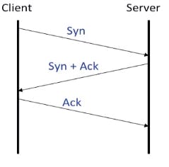
The client first sends an emtpy (no data) TCP segment to the server with the SYN flag set. The sequence number in this case will not be 0 (even though you can see below that wireshark shows it as Seq = 0). It will be a random 9-10 string digit. You can actually disable relative sequence numbers from the Edit - Preferences - Protocols - TCP - and uncheck "Relative Sequence Number". A picture with the "correct" Seq/Ack number will be shown below too. These are the three TCP segments required for the 3-way handshake.


There are good reasons for choosing a random SeqNum: security reasons, so that people can't guess the sequence number and try to insert data; it's also useful against random (corrupt) packets which can overlap with our sequence number.
The server acknowledges the client's SeqNum by sending a segment back with the flags SYN and ACK set. It too, establishes a connection in the opposite direction. The server chooses a random sequence number and for the acknowledgement number it will pick the client's sequence number + 1.
Finally, the client responds back sending a TCP segment with its ACK flag set. The SeqNum will be its own sequence number + 1 and for the acknowledgement number it will pick the server's sequence number + 1.
Connection teardown
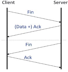
When the client has done sending data to the host, it sends an empty TCP segment with the flag FIN set. The server then sends the remaining data and also sets the ACK flag, acknowledging the fin segment from the client. When the server is ready to close the connection, it sends a segment with the flag FIN set. At this point the client sends the final segment acknowledging the server's fin.
UDP (user datagram protocol)
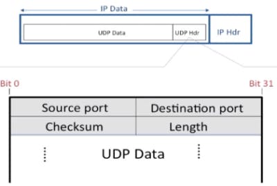
There are also unreliable protocols. UDP is also a transmission protocol which doesn't require the reliability and overhead of TCP. DNS services use UDP for example. A UDP segment is much simpler, as you can see in the image.
ICMP - internet control messaging protocol - is a troubleshooting protocol used for error reporting. An ICMP packet has a TYPE and CODE associated with it. An example of when a host might send an ICMP packet is when the TTL in an IP datagram (explanation follows) is 0. The ICMP packet is constructed by taking the last 8 bytes of the IP datagram + its header, it adds an ICMP Type and Code creating therefor the ICMP segment.
Internet protocol (IP)
The network layer uses the internet protocol (IP). It's an unreliable protocol, which means packets might be dropped in certain circumstances. It's connectionless, meaning that it does't maintain any per-flow state. An example when a packet might be dropped is when the router buffer is full or when the TTL field of a datagram is 0. The network layer has two important tasks: forwarding and routing. Forwarding is the process of moving the datagram from the input link to the output link of a router. Routing is a network-wide process of choosing the path a packet should take. The paths are calculated with the help of routing algorithms.
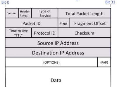
A high level view of the IP datagram looks like the image above.
Version is the IP version (4 or 6).
Header length specifies the length of the header in words (one word is 32 bits).
Type of Service is used to tell how a packet should be services by a router. Read more about it here.
Packet ID has to do with datagram fragmentation.
Flags are the reserved, don't fragment (DF) and more fragment (MF) in this order.
Fragment offset again has to do with ip fragmentation.
TTL is a field which is decremented by each router along the path. It is used to avoid packets looping forever.
Protocol ID basically tells us what type of data it's inside (the most common is TCP). Read more about it here.
Source and destination address are the IP addresses of the two end hosts.
The other fields are self-explanatory (see above from TCP). The actual binary representation alongside with a wireshark screen follows.
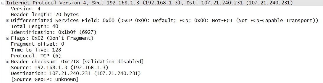
In the screenshot above you can see that it has the DF bit set because generally IP fragmentation is avoided. The IP version is 4 (IPv4), the TTL field is 128 and the protocol is 6 which represents TCP (see here a list of protocol numbers). The header length is represented in words, so it’s 5. Differentiated Services is the Type of Service field, and it's 0. Total length is 40 and it’s meant to represent bytes (so 1 bit in the field means 1 byte in this context). We have 00101000 which equals 40, so 40 bytes. The rest of the field are all the binary representation of what you see in wireshark.
IP has mechanisms for preventing packets to loop forever – the TTL field. When a datagram is sent, each router along the path that receives it will check the TTL field. If it's 0, it will discard the packet and send back an ICMP message with "TTL expired" to the sender. Otherwise, it will decrement the TTL field and send it on its way to the next router.
Packet forwarding
At the network layer, routers are responsible for forwarding the packets to the correct egress link. They do this with the help of forwarding tables. When a packet arrives at a router, that router decapsulates the packet (the reverse of encapsulation) up until the network layer and checks the TTL field. If it's 0 it discards the packet and sends an ICMP message back to the sender. Otherwise it decrements the TTL field and performs a lookup in its forwarding table. These tables are populated by routing algorithms and contain IP - egress link entries (can also contain other information). The lookup is performed on the destination IP but it's not an exact match. Instead, it's what's called a longest prefix match meaning that it will select the longest IP that matches the destiantion IP. If there are 2 IP addresses in the forwarding table: 168.124.x.x and 168.124.65.x and the destination IP is 168.124.65.120 it will match the second one. Afterwards the router will update the header (with the new TTL and checksum) and queues the packet in the buffer for the corresponding egress link